Processing historical aerial photos, revisited

Hello,

I’m revisiting a project similar to one I discussed in this 2018 post, where I had successfully generated a decent point cloud using low-precision Ground Control Points (GCPs). Back then, ODM was using PMVS instead of the powerful SMVS algorithm.

I’m now working on a similar process with aerial photos from the same flight (60% forward overlap, 20-30% side overlap), but covering a different area. I’m using GNSS data generated from double and triple frequency DIY receivers, with millimetric error. The photos are 100 MP, high quality, with a GSD of about 50 cm. To adapt to ODM’s workflow, I’ve created multiple shell scripts and even developed a hybrid workflow I hope to publish soon. This involves using QGIS and GCPEditorPro (a fantastic tool!) for finding common points between the present (e.g., Google Satellite reference images) and the past (in my case, the year 2000). My scripts perform mass tasks like cropping photos, pre-orienting them based on the flight line (useful for using them in GCPEditorPro), stamping EXIF data, among others. This work is promising as it unlocks the potential of underutilized historical photographs.

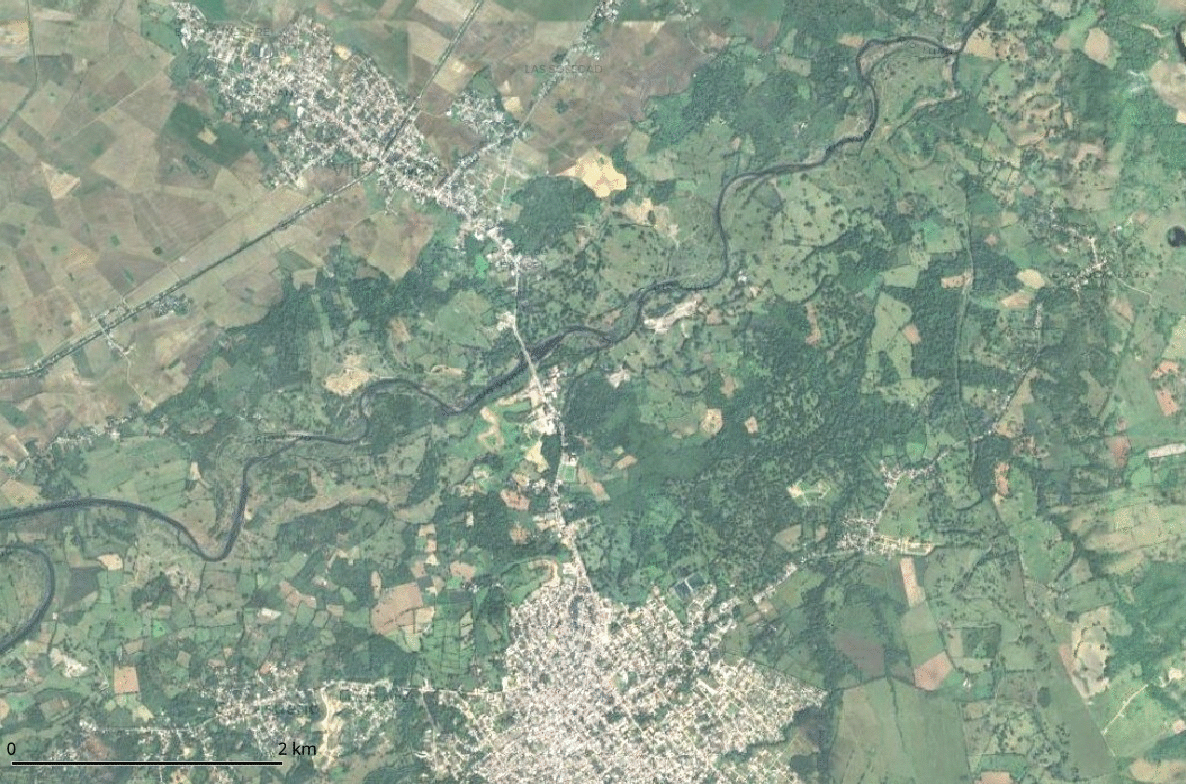
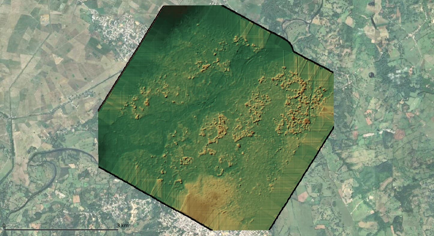
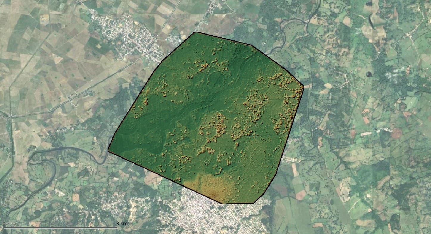
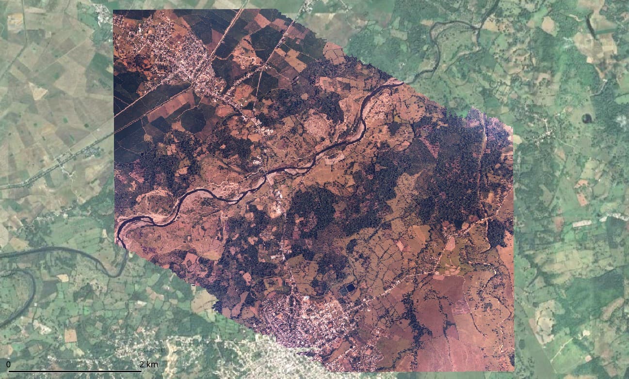
However, I’m facing some issues with the results. As seen below, the orthomosaic is literally perfect.

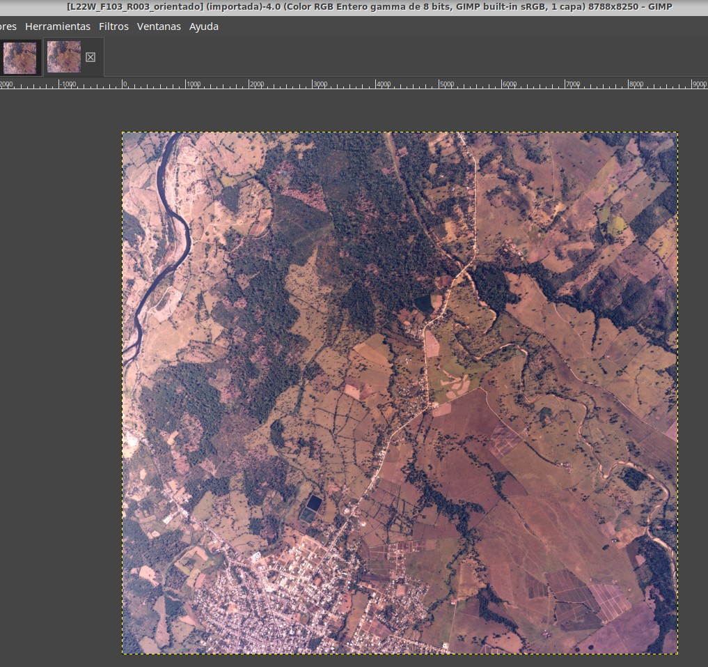
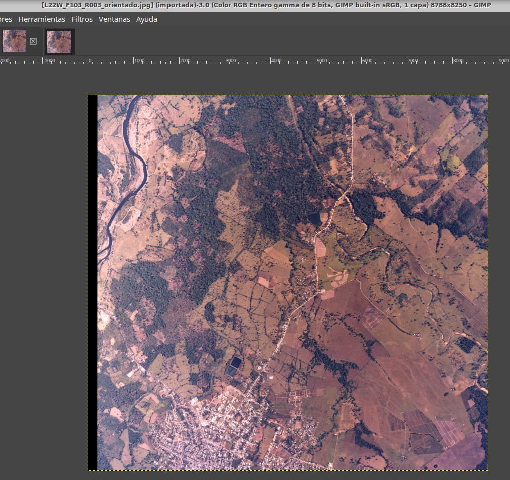
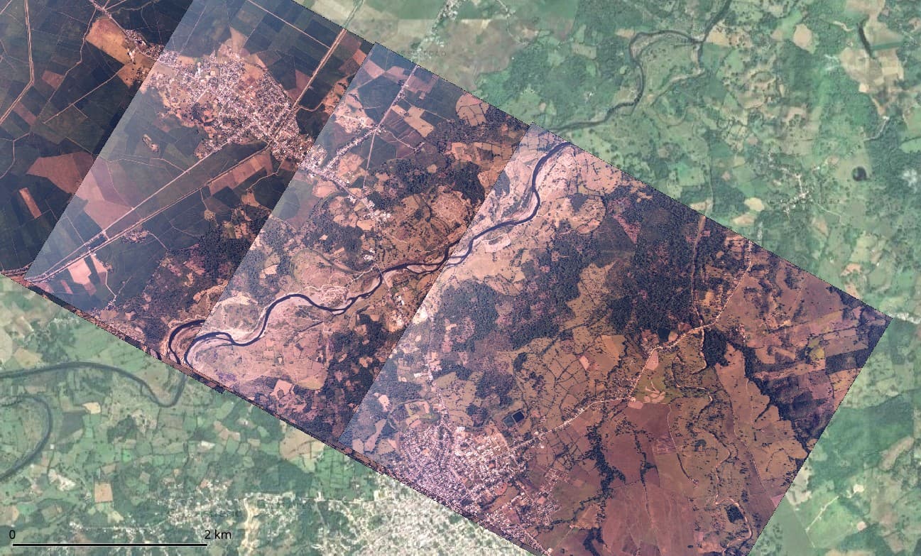
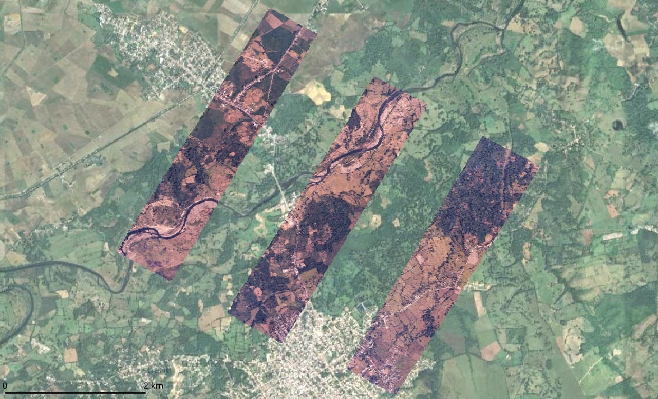
The original photos of the example displayed above, slightly cropped to remove the frame, rotated, and geolocated, appear like this:

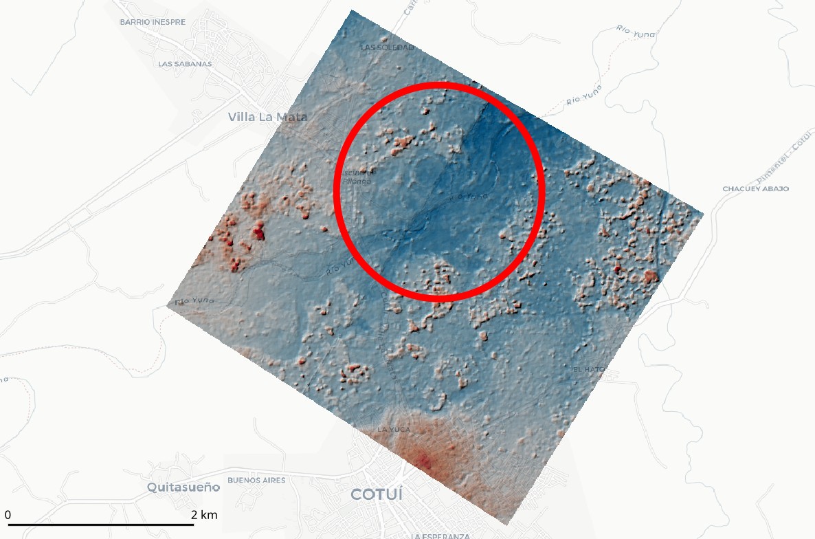
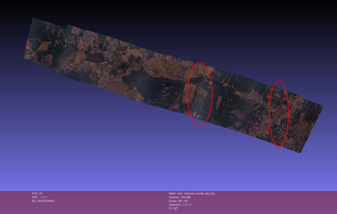
However, the point cloud, and consequently the DSM, is only generated in areas with triple photo overlap, and the accuracy isn’t as expected (detecting up to 2 meters error in vertical components in some cases). See the results below for standard configuration:

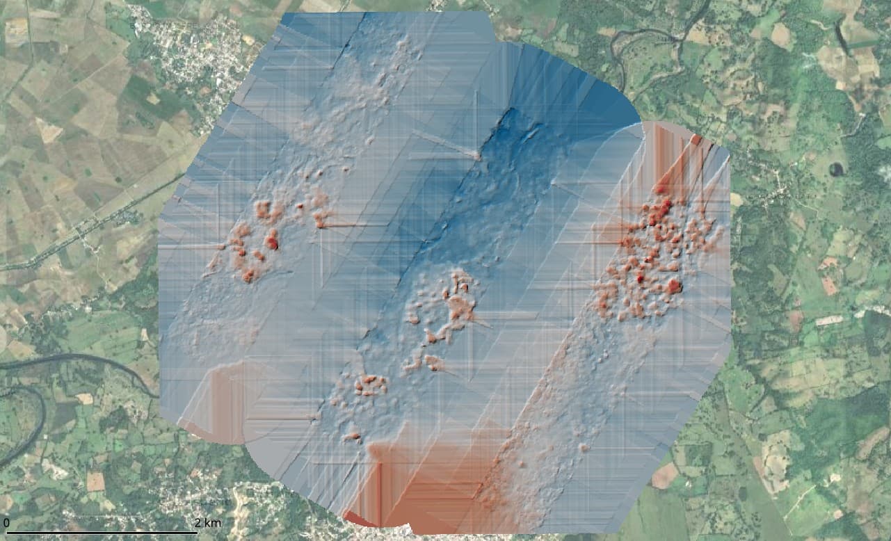
I’ve processed these captures with default options for generating DSM+DTM. In addition, I’ve tried various settings, even without resizing, but with little success. For instance, I’ve experimented with nearly all options mentioned in this post and this one, yet the results don’t improve much, still showing gaps in the point cloud. And when I say nearly all options, I mean that in “pc-quality” the highest I could go was “high”, as “ultra” took over 36 hours on a PC with an 8-thread processor and 64 GB RAM, and I had to stop it. I’m aware that areas with only dual photo overlap are challenging for the current ODM engine, but I’d like to leverage the potential of SMVS or, alternatively, return to PMVS (I recall modifying the depthmap_min_consistent_views option in the config file from 3 to 2).

What are my options with the latest version of ODM using SMVS? As @smathermather mentioned in the 2018 post, PMVS was replaced with SMVS. I understand that executing workflows with legacy PMVS is not possible now, but it was a tremendously useful functionality of ODM for processing historical aerial photos to create dense and precise point clouds. Another question is whether using cloud hardware (e.g., 256 GB RAM and 1 TB of virtual memory) would allow me to apply settings like “pc-quality: ultra” for better results. Should I consider using the old version of ODM or perhaps NodeMicMac?

Any suggestions or insights would be greatly appreciated.

José

2 Likes

Continuing my quest for processing options for the historical aerial photography project with 60% overlap, I came across an option in the Run Time Parameters Wiki that I referred to in my initial post:

  --opensfm-depthmap-min-consistent-views <integer: 2 <= x <= 9>
                        Minimum number of views that should reconstruct a
                        point for it to be valid. Use lower values if your
                        images have less overlap. Lower values result in
                        denser point clouds but with more noise. Default: 3

However, when trying to use this option, with a command like this…

docker run -ti --rm -v /media/jose/datasets:/datasets opendronemap/odm --project-path /datasets test1 --opensfm-depthmap-min-consistent-views 2 --min-num-features 30000 --matcher-neighbor 14 --mesh-octree-depth 12 --feature-quality high --pc-quality high --texturing-keep-unseen-faces --dsm --gcp /datasets/gcp_list.txt

… using, for example, the Docker opendronemap/odm:latest or opendronemap/odm:2.9.2, in the standard output I receive “run.py: error: unrecognized arguments: --opensfm-depthmap-min-consistent-views 2”.

I suspect that the argument was removed in some earlier version, but I have looked through the changelogs of the releases and have not been able to find it. Which was the last version in which this argument was available?

José

1 Like

I missed when that was removed, but you can modify that behavior directly in the config.py for OpenSfM:

2 Likes

Thank you for your guidance on adjusting the depthmap_min_consistent_views parameter in OpenSfM’s config.py.

I have a concern, however. Based on my understanding that dense point cloud generation primarily depends on SMVS, I’m uncertain whether altering this parameter in OpenSfM will influence the results. In fact, I’ve created a new Docker image incorporating this change, yet observed no difference in the outcome. Is there a way to configure SMVS to specifically generate dense point clouds in areas with only two overlapping images, or is there another strategy you would recommend?

1 Like

I’m continuing my exploration into processing historical aerial photographs with a specific focus on point cloud densification in areas visible in only two views. From my previous discussions and research, I’ve gathered that OpenMVS handles the densification process, and the --number-views-fuse argument seems to be particularly relevant for my case. The default value of this argument seems to be 3 in the OpenMVS repo source code.

I’m working with an OpenDroneMap (ODM) setup, specifically within a Docker environment. Based on my undertanding, the --number-views-fuse parameter is passed to OpenMVS through the /code/stages/openmvs.py script during execution. While reviewing the console output from my processing, I noticed that --number-views-fuse 2 is indeed being sent to OpenMVS. Logically, this setting should enable ODM to densify the point cloud in areas that are only covered by two views. However, contrary to expectations, it appears that densification is only occurring in areas with at least three views. The relevant console output is as follows:

[INFO]    running "/code/SuperBuild/install/bin/OpenMVS/DensifyPointCloud" ... --number-views-fuse 2 ...

So my question now is: where else I should look to determine why ODM is only densifying areas with a minimum of three views, despite the apparent configuration for two views?

Any guidance, suggestions, or insights into what might be causing this discrepancy would be greatly appreciated.

1 Like

Good catch – sorry for the OpenSfM redirect. That would only influence the sparse point cloud.

Can you provide some screenshots of what you’re seeing WRT only 2 views?

1 Like

Thank you. I found a possible solution. Currently, I’m performing some tests, and will post the results shortly.

2 Likes

After multiple tests, I am posting my solution to the problem of point cloud densification in areas with only two image views (I’m including some results below).

As indicated in this OpenMVS issue, using the --number-views-fuse 2 flag does not guarantee that OpenMVS will densify areas with only two views. According to the OpenMVS developer, it’s necessary to add Min Views Filter = 1 to the Densify.ini file, but the --number-views-fuse 2 flag should still be included at runtime. This enables the option of not dispensing with filtering in post-processing, allowing for depth map fusion in two-view areas. In the openmvs.py file, the --number-views-fuse flag is hardcoded to 2, so I think it’s unnecessary to add this change, and only the Densify.ini part is needed. This could, in fact, explain some issues other users have reported in flights with little overlap.

To incorporate these changes in the ODM toolkit, I modified the openmvs.py file in my ODM fork, two-views branch. I realize these changes might be only useful for me, but I share them in case someone else faces this issue of low overlap in frames, especially useful with historical aerial photographs.

openmvs.py (for densification):
Link to openmvs.py changes - Line 64-65
Link to openmvs.py changes - Line 98

I tried to make changes to the Densify.ini as “respectful” as possible, preserving other configurations and only adding the one I was particularly interested in (Min Views Filter = 1). This explains the use of a+.

Following @smathermather recommendation, I also modified config.py file, which I did inside a container and then created my own image afterwards:

sed -i 's/depthmap_min_consistent_views: int = 3/depthmap_min_consistent_views: int = 2/g' \
  /code/SuperBuild/install/bin/opensfm/opensfm/config.py

Below is an animation showing the obtained DSM and the orthomosaic. To improve execution times, I tested with only three frames, but still, the GSD of 47 cm was perfectly maintained (1 million points extracted), and the products turned out well with that resolution. The orthophoto aligns flawlessly with the reference image, yielding an exceptionally precise result

gif

My configuration to launch the container was basic for DSM + DTM, but using a container generated from my own image with the modifications made to the config.py and openmvs.py files:

docker run -ti --rm \
  -v "$(pwd)"/datasets:/datasets odm_min_views_2 \
  --project-path /datasets test1 \
  --auto-boundary \
  --dsm \
  --dtm \
  --pc-quality high \  --gcp /datasets/gcp_list.txt | tee salida_v3.4.0.txt

Now, I need to determine why two undesirable errors are occurring, which I understand are minor, but I need to resolve; any help you can provide is more than welcome. These are:

  • A seam in the center of the area (running SSW-NNE), which creates a notable bias in the point cloud and, consequently, in the DSM. This seems to be due to the overlap from an area covered by three views to one covered by only two views. I think it could be resolved by keeping the outer frame of the original photos (leaving a larger buffer area for better blending), instead of providing pre-cropped images. I guess that the blending that ODM does is powerful enough to detect the frames tipycally found in historical aerial, so it should ignore them.

  • GCPs with significant displacement. Four GCPs (out of nine) show a lot of deviation in Z, in some cases up to 8 m. This is not acceptable in my case for two reasons: the model is for hydrological purposes, and the GNSS receivers are giving me solutions with errors just in millimeters. I don’t have a clear answer to the problem, and I would prefer not to resort to omitting Z in these points, as these elevations are quite accurate. I’ve also considered using “–pc-quality ultra,” but I don’t think it would have a significant effect.

As happened in 2018, ODM continues to be the most versatile tool for these tasks. I once again congratulate the developers at the forefront.

4 Likes

If you resolve those issues, do you think you might make a PR with your change for min-views?

2 Likes

Absolutely! If I successfully resolve these issues, I am more than willing to submit a PR with the changes I’ve made for min-views.

Thanks for considering the potential of these changes.

4 Likes

It isn’t my usage pattern right now, but my County has incredible historic imagery so I am interested. I am sure other folks are looking with interest, as well.

Being able to ingest such data is also broadly valuable and sought-after, so we absolutely appreciate help here provided it does not break existing workflows and processing quality.

4 Likes

this is miles above my pay grade lol Wow what a cool solution to your project!

2 Likes

Hello again,

Thanks everyone for your responses and tips on my last post. In this new post, I wanted to share some updates and seek guidance on the seam issue I’ve posted in my last message.

As far as I can determine, this stitching issue stems from a problem in the reconstruction stage of OpenSfM. This was also suggested by the OpenMVS developer in the issue I opened on the OpenMVS repo. The developer recommended trying reconstruction with software other than OpenSfM (e.g. COLMAP), but I haven’t had success with this approach.

Exploring OpenSfM’s results further, I noticed that images in the undistorted directory have a “mysterious” black strip on the left side, which seems to be causing the problem. Removing distortion is a geometric process that should not add a strip but merely alter geometry. However, I can’t figure out why this black strip is appearing, especially since normally the undistorted images in the ODM workflow do not have such an addition. Below are the help captures:

Original Image Capture:

Undistorted Image Capture:

I would appreciate any insights on which parameter needs adjustment to prevent the addition of this black strip. I’ve tried modifying the config.py in OpenSfM, setting the resize to -1, but without success.

Thank you for your assistance.

1 Like

Hello,

I am persisting in the challenge of using OpenDroneMap (ODM) to achieve quality reconstruction and generate a reliable Digital Surface Model (DSM) from historical aerial photographs with low overlap. Here’s what I’ve tried and found so far:

  1. I created a custom image of opendronemap/odm to make OpenMVS consider areas with only two views in densification. This worked, but the DSM still had an artifact - a seam between areas with two and three views.

  2. I experimented with multiple OpenMVS configurations related to the special densification I’m aiming for, but unfortunately, the seam between the two and three view areas persisted.

  3. I attempted some changes in OpenSfM configurations, to no avail. However, I doubt the issue lies with OpenSfM, as the filtered point cloud (odm_filterpoints/point_cloud.ply) doesn’t show the mentioned artifact. It’s unclear to me if this filtered point cloud is part of the processing flow.

  4. I tested with three photos from a Phantom 4 flight, not using consecutive photos but only the even ones. This simulated the low overlap conditions of the historical photos. Surprisingly, the result had no seam, suggesting the problem might not be introduced by OpenMVS in densification or by OpenSfM, but could be due to the geometry of my photos. This leads to the possibility of an inadequate distortion correction (“undistortion”) being the culprit. This seems plausible, considering that historical aerial photography cameras had large CCDs and focal lengths (each frame being about 100 MP).

  5. Related to the above, my hypothesis centers on the undistortion process, though I’m not entirely sure if this is the only aspect to consider. I noticed that this process adds a black band on the sides of the photos (see above), which shouldn’t happen. Removing distortion should alter the shape of the capture, not add bands at the edges (I believe this is done by cv2).

In summary, I’ve run out of options and lack a clear direction on how to proceed. I am keen on keeping my project within ODM, but cannot use a DSM with the aforementioned artifact. I would greatly appreciate any suggestions or guidance on where to explore next.

Thank you all in advance for your help and insights.

1 Like

Do you have a fork of ODM and data to share for testing? I have some hunches, but iterating on them will be faster with something to play with.

Awesome progress. I suspect we can get you the rest of the way.

4 Likes

Wow! Thank you for your support.

Indeed, I have a good number of images for testing. To keep things simple and consistently evaluate changes when making adjustments, I always test with the same three images. I have placed them in this Drive folder: https://drive.google.com/drive/folders/1iyz5r77kC-2JEoj9gutm_Fa4yiABDaKp?usp=drive_link

The photos I am using in all the tests can be found in use-this-cropped. These images were cropped with certain control, as I tried to frame them right at the fiducial corner marks. I also slightly deformed them with a thin plate spline to approximate the marks to the positions they were supposed to occupy (nominally, a frame taken with a Leica Wild RC-30 15/4 UAG-S, measures 212 mm between corner marks). As I say, using these cropped images, the results are slightly better than if I used the original images or those cropped arbitrarily. However, I have not managed to eliminate the seam artifact.

For archival purposes, I placed the original frames in the “originals” subfolder; these contain supplementary information, as well as a black border, both of which hinder reconstruction and are not recommended for such purposes.

Accompanying the images in the use-this-cropped subfolder, I included a GCP file with coordinates taken by multi-frequency GNSS, with millimetric error.

On the other hand, my modifications to ODM and OpenSfM are included in this Docker image: https://hub.docker.com/r/jmartinez19/odm_min_views_2

With this command, I get an acceptable result, but the seam is visible in the DEM and in the textured image.

docker run -ti --rm \
  -v "$(pwd)"/datasets:/datasets jmartinez19/odm_min_views_2 \
  --project-path /datasets test1 \
  --dsm \
  --gcp /datasets/gcp_list.txt | tee log.txt

This was the resulting DEM:

And with this, I get an improved result, but the seam is still visible (I have not been able to assess in detail whether filtering the point cloud to 1 sd helps much or little, but it seems that it does).

docker run -ti --rm \
  -v "$(pwd)"/datasets:/datasets jmartinez19/odm_min_views_2 \
  --project-path /datasets test1 \
  --auto-boundary \
  --dsm \
  --feature-quality ultra \
  --pc-quality ultra \
  --min-num-features 20000 \
  --mesh-octree-depth 12 \
  --pc-filter 1 \
  --texturing-keep-unseen-faces \
  --gcp /datasets/gcp_list.txt | tee log.txt

The DEM:

For what it’s worth, the only changes I made to the ODM image were the following: I modified the openmvs.py file so that when creating the Densify.ini file, densifications in areas with only two views are allowed. Also, I modified the opensfm/config.py file in my image. These changes are explained here (quoting a previous message from this thread):

I also made some other temporary adjustments for testing purposes on openmvs.py, but I didn’t save them as they didn’t seem to have any effect.

Thanks again for the support.

3 Likes

First of all, this is a brilliant approach and the steps to reproduce are among the best I’ve encountered.

I’m using exactly your docker image and getting the dreaded:

The program could not process this dataset using the current settings. Check that the images have enough overlap, that there are enough recognizable features and that the images are in focus. The program will now exit.

Which is what I’d expect from just 3 images. Are you able to get it to run with just 3?

But, let’s discuss a bit strategy, because I think I know the source of your seam:

I would recommend rather than GCPs, you use frame-on-center values in a geo.txt file. This allows you to not do any splining of the image. A thin plate spline of the images, no matter how correct the fiducial marks, will make it impossible to get a reliable calibration of the camera.

Secondary to that, lots of images will better estimate calibration and reduce the likelihood of seams than a handful of images. Aim for 15 or more if possible, 5 at the very minimum. Something that’s not too slow to iterate on, but gives statistical robustness to any estimates.

Between the two, I strongly suspect your seams will go away. And if you share me more raw images (I’d be very careful cropping, no splining) I can run some tests. I’ve got some decent compute to throw at it if having 15 or more images is a problem for testing on your end.

3 Likes

First of all, thank you for your support and for taking the time to find solutions.

I have successfully executed the ODM processing flow with my custom image without significant issues. I’m not sure why it didn’t work for you. To address the problem, I’ve uploaded the results of a successful run to this subfolder on Drive:

https://drive.google.com/drive/folders/1QffeBhkFJ90qx98KMoKGIwWWGjIOCND4?usp=drive_link

Moving on to your suggestions, which I find very precise and promising, I have a few questions:

  1. I understand that the initial step is to crop the original images without splining, ensuring precise calibration. I wonder if it’s important to keep the crop size consistent across files, emulating what modern cameras do (same pixel size for all images).

  2. The accuracy of the camera center coordinates is a bit uncertain for me. I see that the geo.txt file requires these coordinates but also allows specifying precision. With historical aerial photographs, pinpointing the camera center coordinates, especially the height (geo_z), is challenging. Would specifying 100 in vert_accuracy significantly impact the results? I know I can estimate the flight height using the nominal scale and focal length; if high precision is necessary, I would do it, but I’d like to know if it’s essential to be accurate in the first instance.

  3. Perhaps I’m mistaken, but is the strategy to, once the camera calibration file (cameras.json) is produced, reprocess using this file but specify GCPs? I ask because the precision of the final result, through GCPs, is very important to me.

I will prepare a set of 15 images, minimally cropped, without splining, along with a geo.txt file. I’ll upload this set to Drive and notify you, thanking @smathermather in advance for any support in facilitating the processing (I read in a forum post about the computer with over 700 GB of RAM, wow!).

1 Like

Yes: I would keep the crop size exactly the same across files.

I think you can safely set the geo.txt coordinates as best as possible with a good accuracy estimate, and if you need additional refinement, you use GCPs to do so.

It’s worth trying first without GCPs for the sake of troubleshooting.

2 Likes

Thank you for your responses and the helpful tips for making progress.

I selected the images and created a comprehensive geo.txt file. I’ve placed both uncropped (in the originals subfolder) and cropped images (in the cropped subfolder) in this Drive folder. Each subfolder includes the corresponding geo.txt file. I appreciate any support in attempting to reconstruct this relatively large dataset.

I’ve conducted several tests using the geolocation file strategy, but I’m still struggling with the issue of stitching not completely disappearing. It seems to reduce slightly, but not entirely.

For the sake of reproducibility, here’s the command I’m using to process the photos:

docker run -ti --rm \
  -v "$(pwd)"/datasets:/datasets jmartinez19/odm_min_views_2 \
  --project-path /datasets test1 \
  --dsm \
  --geo /datasets/geo.txt | tee log.txt

I’m not sure if the files I uploaded to the Drive are sufficient for testing, but please let me know if there’s anything else you need.

I have a question following smathermather’s last message:

It’s not clear to me if I can improve accuracy using GCPs, nor at what point in the process it would be advisable to incorporate them. I understand they can’t be included when processing with geo.txt, as they are two different approaches. So, I’m wondering when I could incorporate them. This is crucial for me, as I’d like the final product to be as accurate as possible, ideally close to the precision of the GCPs.

Another question that arose is whether, when using the geo.txt, it’s possible to preserve the EXIF metadata in the image files.

I appreciate any further guidance.

1 Like