Hi everyone,
I’m trying to generate thermal orthophotos of photovoltaic plants using WebODM, from images captured with a DJI Mavic 3T.
The missions were planned with 80% side and 85% front overlap, flying at 12 m above the panels, with a resulting GSD of 1.59 cm according to the mission planner.
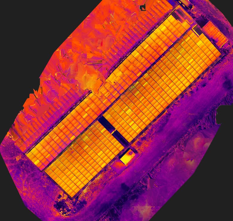
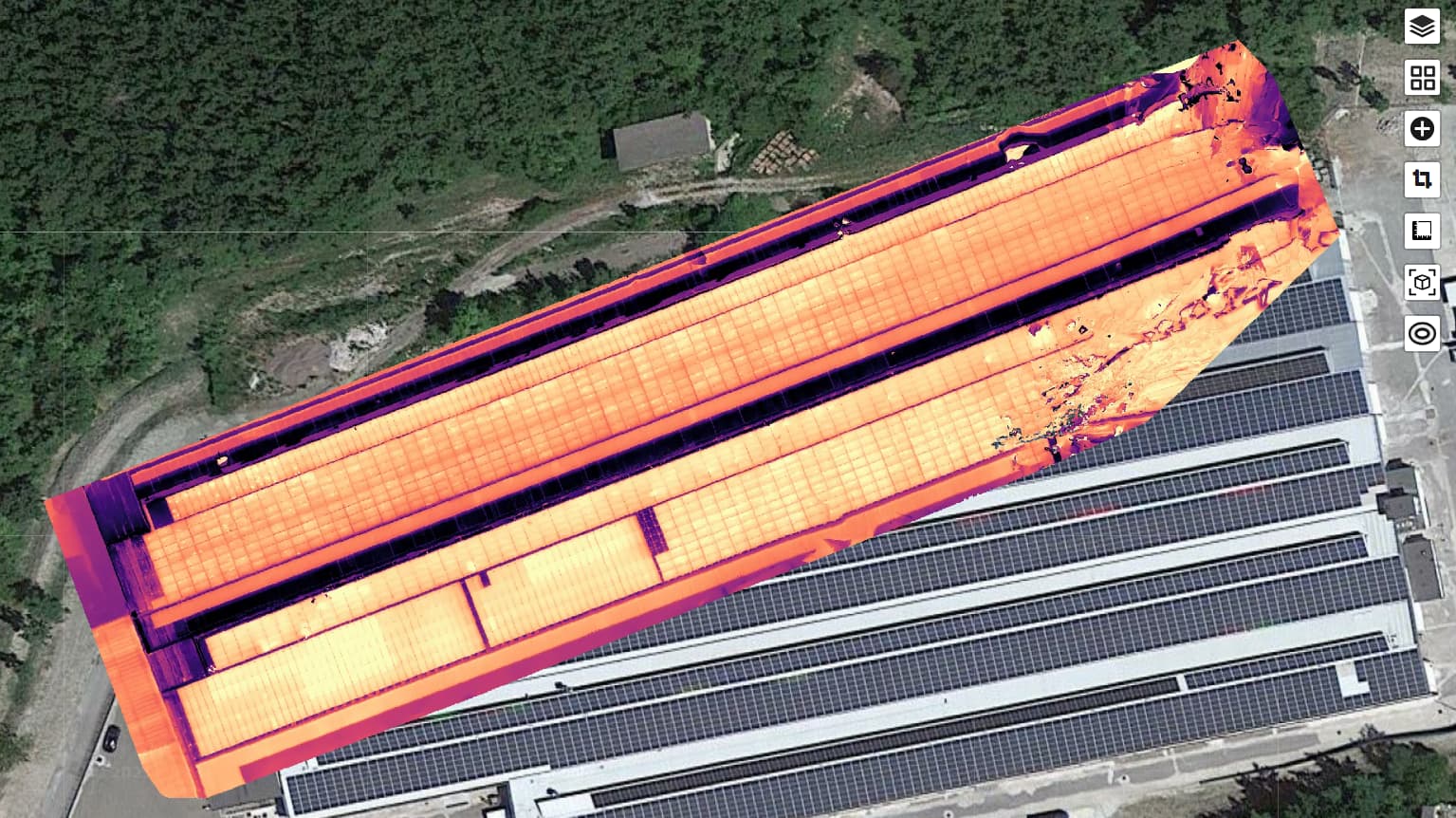
The issue I’m facing is that the resulting orthophoto shows strong distortions, especially in rooftop PV installations, where the panels appear warped and the surfaces are not well represented.
Here are the parameters I’m currently using:
dem-resolution:2
dsm:true
feature-quality:ultra
matcher-type:bruteforce
mesh-size:500000
orthophoto-resolution:2
pc-quality:ultra
radiometric-calibration:none
rerun-from:dataset
skip-report:true
use-3dmesh:true
I suspect the problem might be related to my parameter choices.
Does anyone have suggestions on which settings I should adjust, or best practices specifically for processing thermal orthophotos of PV plants (especially on rooftops)?
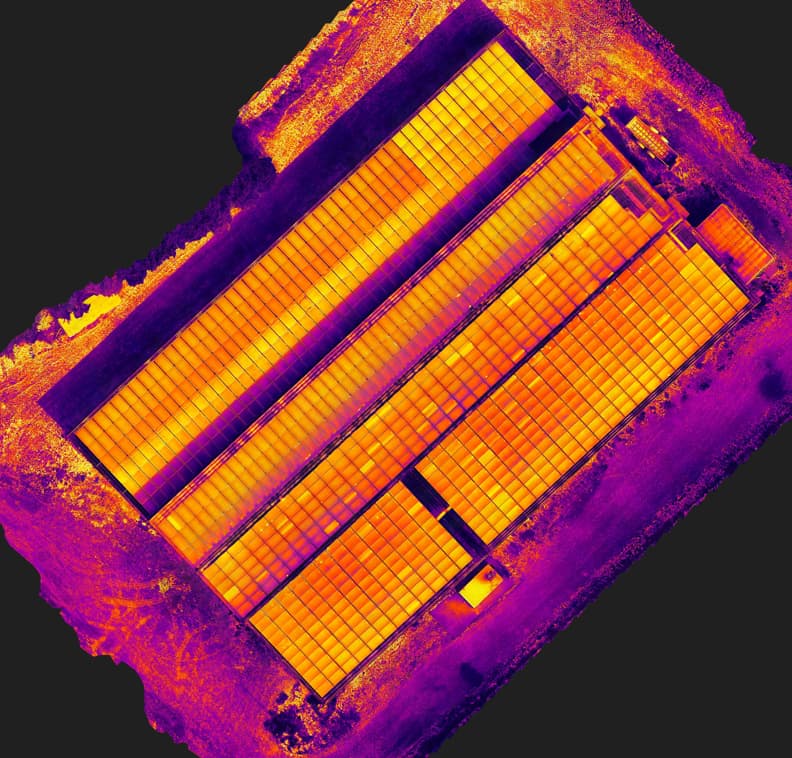
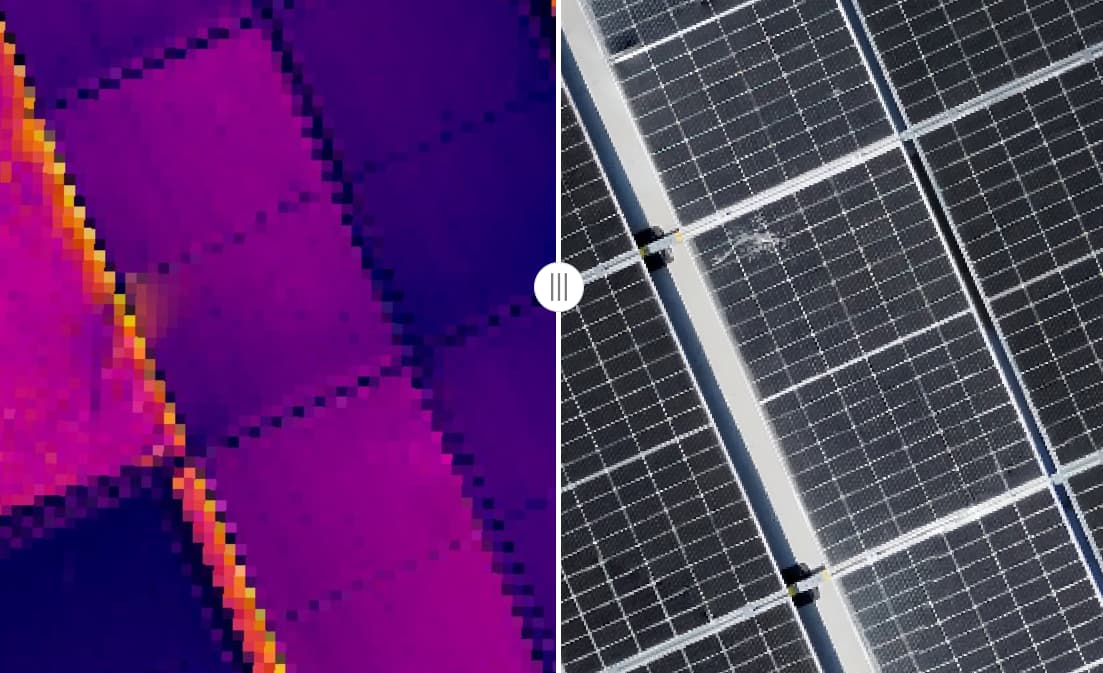
Now I’m attaching one image processed with ODM that shows distortions, and another one processed with the same dataset using a different software, which came out perfectly.
i think warping comes from excessive tilt angles , especially when the object is far from the camera
i saw this warp the other day when a railroad track melted in the model… it was not in my direct field of view … also i think yawing while capture with steep angles may cause this
i know when i add photos of 60-45 deg of tilt the problems creep in
Thanks for the insight! All of my images were captured at 90° (nadir), yet I’m still seeing distortions, particularly on rooftops with multiple height levels. It seems like the varying heights of the panels might be contributing to the warping
Do you think adding a flight with 45° angled photos could help reduce these distortions, or would it make them worse?
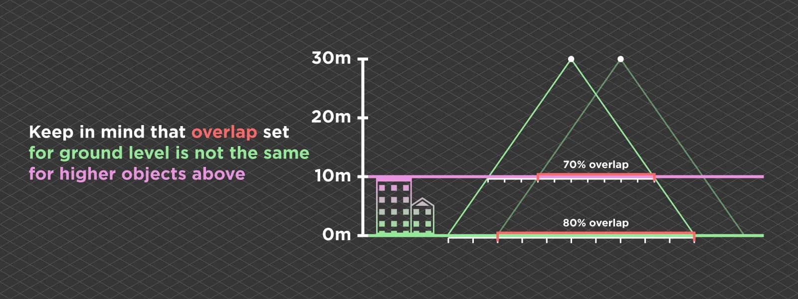
Overlap
Keep in mind that when you configure your flightplan the GSD is calculated based on the ground(elevation), in your case 12mtr. If there are higher objects (such as roofs/panels) in your mapping area that are the “actual area of interest” the distance between the drone and this roof is less than 12 mtr (and so no 80% overlap between the camera and object).
I know there is a setting in the DJI Pilot 2 app, where you configure your mapping area, overlap etc, that you can give an offset altitude, regarding your take off altitude. I guess it’s in the advanced settings where you configure your GSD / overlap. (I don’t have a controller in my vicinity).
I found this nice image that represents the topic:
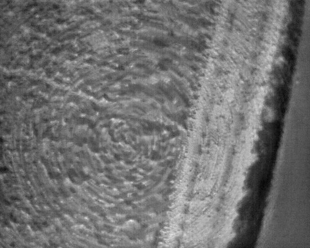
Speed
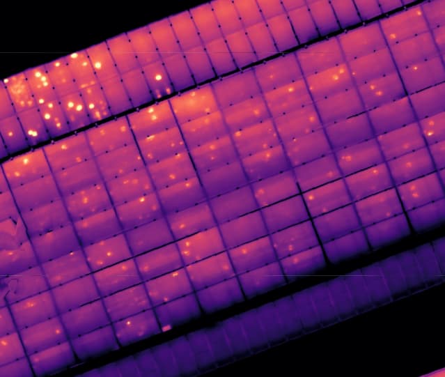
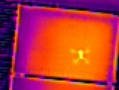
Another thing you can check is your flying speed. In my opinion I find that DJI is pretty optimistic about the “speed to fly” a mapping. Especially the thermal camera is sensitive to motion blur.
This is an example of an thermal image taken at the same time the drone rotated to go back. You can see the circle like distortions in the image.
There is also a setting in your controllor to completely stop the drone when taking an image. That is a nice option, but your mapping will take (much) longer.
Altitude
Do you need the 1.5cm GSD for a thermal image? In my experience you get better thermal mapping results when you fly a bit higher (less motion blur and more overlap). Especially with the align function it’s very nice to use the (low) res thermal images to check for hotspots and use the high res RGB images to give a better visual check. (Is it dirt or a thermal defect?)
Thank you very much, your response was very helpful and made me think. Indeed, in the example I showed, the GSD was calculated relative to the ground, so the highest parts of the roof did not reach 80% overlap.
For this reason, over the past few days I conducted another case study: this time I took 1,300 photos to map an entire rooftop installation, flying 12 meters above it. In this way, the GSD and overlap settings should be correct.
Unfortunately, even in this case the results were still “disappointing.” For my project workflow, I really need high-quality images with the iron red palette.
The parameters I used are always the same:
dem-resolution:2
dsm:true
feature-quality:ultra
matcher-type:bruteforce
mesh-size:500000
orthophoto-resolution:2
pc-quality:ultra
radiometric-calibration:none
rerun-from:dataset
skip-report:true
use-3dmesh:true
I’m not sure if anyone has different suggestions for the settings.
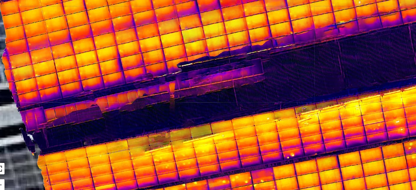
Unfortunately, I can’t process all 1,300 photos, so for now I selected a smaller section, sampling around 300 images.
I’m linking the result here, and you can notice some distortions on the panels.
Great, thanks! Here is the link to my Drive folder: volo2 – Google Drive
I’m currently uploading the images, the full set should be available in about an hour.
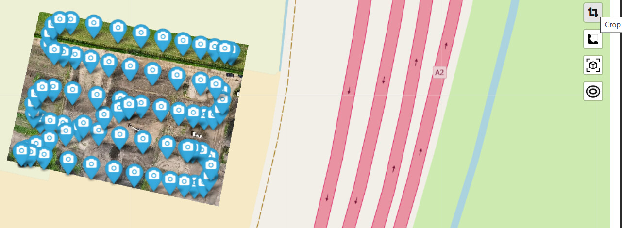
Hi I did some tests. I didn’t use all the images. The images DJI_20250904123030_0083_T till DJI_20250904123137_0150_T were so called oblique images. For this mapping I used only the nadir images.
JPEG
With some cropping I got a first result. I saw a pretty big gps offset and the mapping isn’t that good in the eastern part.
The nice feature with the converted images is that you can use the sliders to play with the temperature range. I didn’t know the local environment settings (temp / humidity) so i left the Thermal-Tools convertor with the default settings.
first of all, thank you so much for all the tests you’re running. This is really helpful for me and I’m learning new things from your explanations.
About the oblique images: on my DJI controller I usually keep the option called something like “optimization elevation” enabled, which automatically captures some oblique photos. Do you think it makes sense to include those images in ODM, or do they actually make the final result worse?
Regarding the TIFFs: is there a real difference between using the original JPEGs and the converted TIFFs? If I generate an orthophoto from the TIFFs, will I end up with a thermal orthophoto containing all the temperature values?
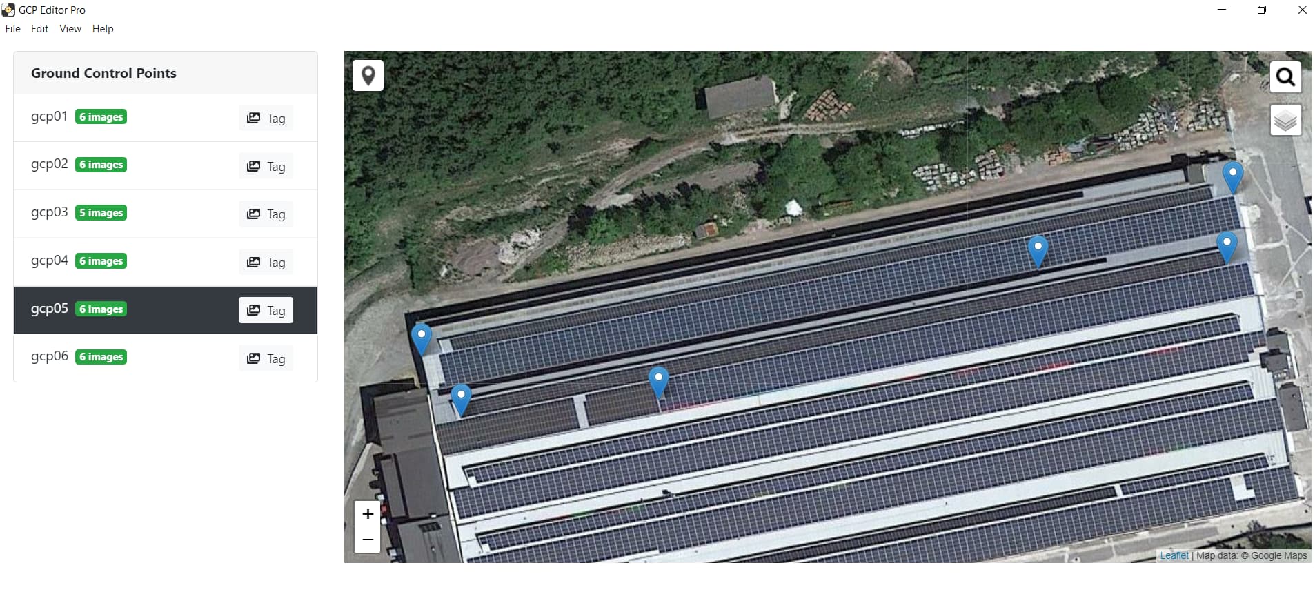
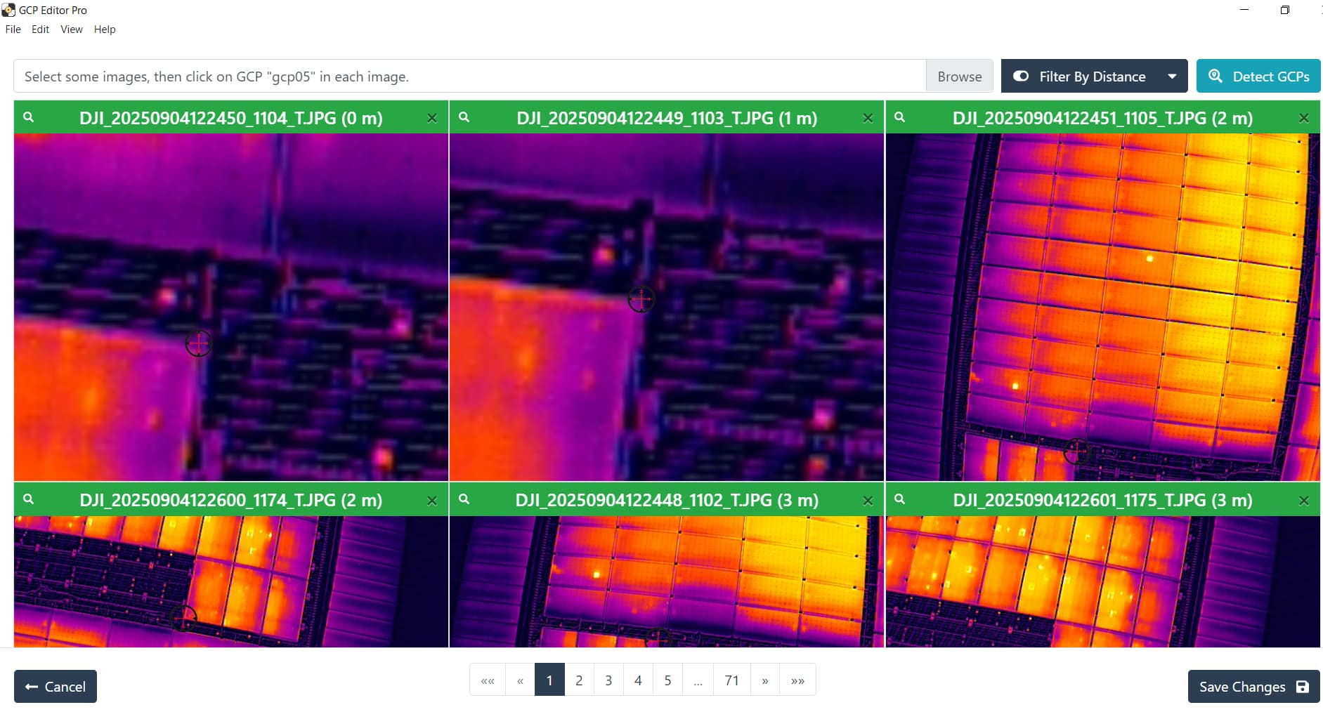
As for the GCPs, I’ve never used them because I haven’t studied that part yet, but I would like to understand if they can also improve the final result significantly.
Thanks again for your time and for sharing your experience
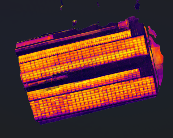
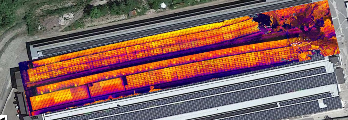
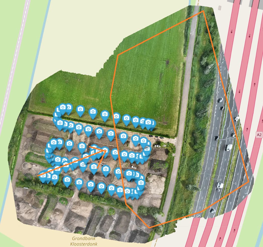
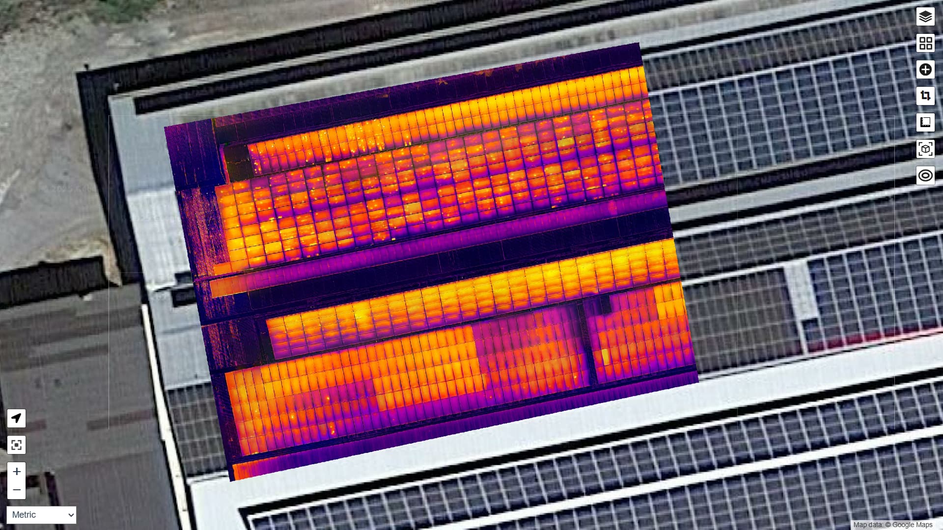
The optimization elevention indeed capture some of these oblique images. I use them too (with RGB mappings) but make sure to use the crop function. Although it should improve your accuracy in your area of interest it has a side-effect. This is because you get a large area (outside your area of interest) that is also mapped due to these oblique images. In my example you can see the last route of the mapping (orange arrow) and the resulting area, within the orange lines, that is being mapped. This area has a lot of distortions.
I processed them individually to see if that is different from your complete set. The left set seems nice. If you didn’t use RTK I guess the result is within the expected absolute accuracy (several meters offset)
Thanks a lot for your detailed reply! That actually explains something I was wondering about – I noticed those oblique areas appearing outside my area of interest, and now it makes sense.
I’m very curious to see your final result, and if you don’t mind sharing, which processing parameters did you use for the orthophoto?