Lens calibration of thermal camera DJI 3T?

Hey there ODM community!

I’ve been a busy reader the last few days! First off - this community is really neat, thank you all for your help and interesting posts.

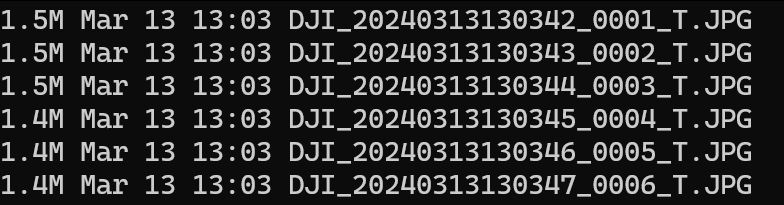
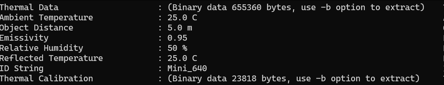
My use case for ODM is thermal mapping of solar power plants with a DJI Maivc 3T for inspection. Capturing thermal images with said drone is super easy, converting the proprietary :melting_face: thermal data for radiometric calibration sadly is not. Got it working though, if anyone is interested I can share how.

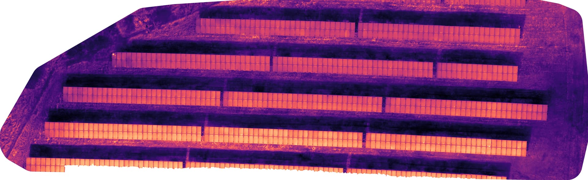
The thermal images from the 3T are kinda distorted (fisheye-ish), sample (not converted to tif yet, rJPEG):

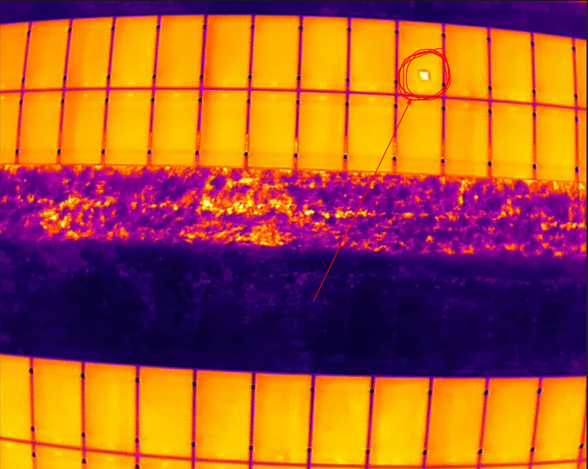
Also see that beautiful hot spot I marked there. This is why thermal inspection is really important.

For normal RGB-images the distortion can be removed by lens calibration and similar means, for thermal it works the same but I am kinda struggeling with the camera parameters ODM automatically chooses. They are always different, even for the same project when rerun. I’d love to take that factor out of the processing of the orthophotos.

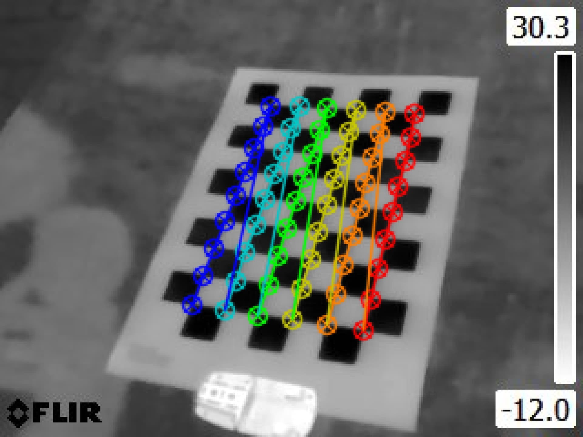
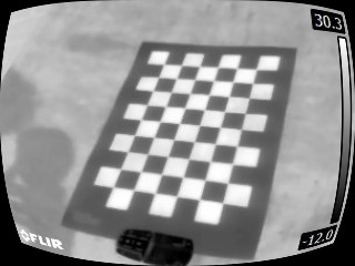
Do you think it would be a smart idea to manually calibrate the thermal lens? I thought about creating a checkerboard pattern with alternating black and white paint in the sun or something and using adobe lens profile creator. Does it actually make sense manually calibrating the lens or should I watch other parameters?

Also - any help for high detail thermal orthophoto creation would be really appreciated!

Have a good one!

1 Like

We have a lot of folks that would benefit from this knowledge, so if you can share it, especially to our documentation, that would be amazing!

It may not hurt, especially if things are too variable that they are disrupting reconstruction for you.

What parameters are you using, and what are the specifications of the input thermal data?

Thank you for your reply!

Since it’s a wacky workaround I’m using, it’s kinda unfit for official documentation, I think. but with more work put into it, it could find it’s way there, imho. For now I’ll just share it here.

The DJI 3T uses the H20T camera, producing thermal and RGB-images. The default output files look like this (“T” for thermal):

Sadly DJI uses some proprietary bs thermal-data-fomat, as other users in the exifforum (DJI H20T thermal radiometric jpeg file) have noted too, see (it’s contained in the binary data):

Thankfully another user has solved the issue of converting the binary data to an array of thermal values, found his repo on github: GitHub - SanNianYiSi/thermal_parser: FLIR/DJI IR Camera Data Parser, Python Version
It still needs the proprietary DJI-SDK for converting the data though which can be found here: DJI Thermal SDK - Download Center - DJI

Using the github repo I wrote a super simple script which converts all the images in the folder in which the script is run to 32-bit .tif-files with proper thermal data. It will place the processed images in a subfolder called “processed”.

# conv_script.py
import glob
import numpy as np
# the thermal.py script from https://github.com/SanNianYiSi/thermal_parser/blob/master/thermal_parser/thermal.py needs to be in the same folder as this script
from thermal import Thermal
import tifffile as tiff
from tqdm import tqdm

# path to the DJI SDK /bin folder
directory='/path/to/proprietary/dji_thermal_sdk_v1.4_20220929/utility/bin'

# you gotta adjust the paths to the libdirp-library according to your linux distro, for Arch it is:
thermal = Thermal(
    dirp_filename=directory + '/linux/release_x64/libdirp.so',
    dirp_sub_filename=directory + '/linux/release_x64/libv_dirp.so',
    iirp_filename=directory + '/linux/release_x64/libv_iirp.so',
    exif_filename=None,
    dtype=np.float32,
)

# use only thermal jpegs in the current folder
jpegnames = glob.glob('./*_T.JPG')

# create a nice progress bar in the terminal, since it might take a while to process
with tqdm(total=len(jpegnames)) as pbar:
    for fname in jpegnames:
        temperature = thermal.parse_dirp2(image_filename=fname)
        assert isinstance(temperature, np.ndarray)
        tiff.imwrite('./processed/'+fname[:-4]+'.tif', temperature)
        pbar.update(1)

This will create a set of untagged .tif-images, missing GPS and all other info of the cam/drone. So we copy the tags from the original JPG-files to the .tif-files with (run in the directory with the original files inside:

exiftool -overwrite_original -tagsfromfile ./%f.JPG -all:all ./processed/

For ease of use I wrote a sloppy bash script to run both the converter and tag copy commands:

#!/usr/bin/env bash

echo "Now converting thermal jpegs to .tif!"
mkdir ./processed
python conv_script.py
echo "Copying tags to created .tifs, please be patient..."
sleep 5
exiftool -overwrite_original -tagsfromfile ./%f.JPG -all:all ./processed/
echo "Done!"
sleep 5

The file structure in the folder in which the script is run should look like this (thermal.py is at the bottom of the folder):
grafik

The solution is not exactly pretty but works for me at least. :slight_smile:

3 Likes

I got okayish results with: auto-boundary: true, camera-lens: fisheye_opencv, feature-quality: ultra, gps-accuracy: 2.5, min-num-features: 70000, optimize-disk-space: true, orthophoto-resolution: 0.01, radiometric-calibration: camera, use-fixed-camera-params: true

In detail it is still looking wonky:

Not perfect, but way better than everything else I achieved so far. The data set certainly is not optimal though. In order to minimize reflections I flew with the cam parallel to the solar modules (~15° or something) and for catching those cell defects I flew pretty low with 80% overlap vertically and horizontally. That’s my flight path:

Ah, and I am still dipping my toes into the whole drone flight orthophoto thing, got no GCPs yet which might be an issue too.

2 Likes

Alrighty, some news from the thermal cam calibration frontline - you actually can calibrate a thermal camera quite easily with OpenCV and a piece of paper. There is a nice tutorial in the OpenCV docs (OpenCV: Camera Calibration) on that. The adjustments I made for thermal cameras are:

  • printing the pattern on a piece of paper (A3 or bigger preferred since thermal cams have a crappy image resolution)
  • laying the piece of paper as flat as possible in the sun (or glueing it to something like a glass pane, dunno)

If the sun is out you get a super nice contrast in under a second here on the pattern.

Test image I’ve taken with one of our handheld thermal cams:


OpenCV found the corners of the squares!

Proof of concept code for undistorting a single image after calculation of the camera calibration values (there is more parameter tweaking to be done, I guess, this is more of a test than anything else):

import numpy as np
import cv2 as cv
import glob

# termination criteria
criteria = (cv.TERM_CRITERIA_EPS + cv.TERM_CRITERIA_MAX_ITER, 300, 0.0001)

# prepare object points, like (0,0,0), (1,0,0), (2,0,0) ....,(6,5,0)
objp = np.zeros((6*9,3), np.float32)
objp[:,:2] = np.mgrid[0:9,0:6].T.reshape(-1,2)

# Arrays to store object points and image points from all the images.
objpoints = [] # 3d point in real world space
imgpoints = [] # 2d points in image plane.

images = glob.glob('*.jpg')

for fname in images:
    img = cv.bitwise_not(cv.imread(fname))
    gray = cv.cvtColor(img, cv.COLOR_BGR2GRAY)

    # Find the chess board corners
    ret, corners = cv.findChessboardCorners(gray, (9,6), None)

    # If found, add object points, image points (after refining them)
    if ret == True:
        objpoints.append(objp)

        corners2 = cv.cornerSubPix(gray,corners, (3,3), (-1,-1), criteria)
        imgpoints.append(corners2)

        # Draw and display the corners
        cv.drawChessboardCorners(img, (9,6), corners2, ret)
        cv.imshow('img', img)
        cv.waitKey(5000)
        ret, mtx, dist, rvecs, tvecs = cv.calibrateCamera(objpoints, imgpoints, gray.shape[::-1], None, None)
        img = cv.imread('FLIR0095.jpg')
        h, w = img.shape[:2]
        newcameramtx, roi = cv.getOptimalNewCameraMatrix(mtx, dist, (w,h), 0, (w,h))
        # undistort
        dst = cv.undistort(img, mtx, dist, None, newcameramtx)

        # crop the image
        # x, y, w, h = roi
        # dst = dst[y:y+h, x:x+w]
        cv.imwrite('calibresult.png', dst)
cv.destroyAllWindows()

“Undistorted” image:
grafik
The undistortion is crappy right now, since the piece of paper wasn’t exactly flat. I just tossed it on the ground and took some test photos. I plan to take out the drone this week and try it’s thermal cam on the calibration pattern. I will tape it to a piece of wood or something, I guess.

Bonus question: Is there a way to turn of the image undistortion in WebODM? I think it will interfere with the pre-processed, undistorted images. Thank you!

Thanks for the update!

Instead of applying the corrections, you could generate a cameras.json from your calculated parameters and input with the images:
https://docs.opendronemap.org/arguments/cameras/#cameras

Alternatively, you might be able to apply your corrections and then feed in a cameras.json which ensures no additional correction.

The first is a tested idea/ recommended approach. The second is a brainstorm / untested.

1 Like

Cameras.json it is! Thank you. :slight_smile: I think I’ll keep this thread in the current journal style, I’ll keep on adding new thoughts, experiences and of course questions. Speaking of which…

Having read quite a few of your blog posts (awesome work, thank you!) you might just be the right guy to ask - Do you have tipps on flight planning for my purpose? I’m aware of different flight pattern for camera self calibration you’ve already described in other posts. The challenge with thermal solar inspection is that you have to keep the camera pointed perfectly orthogonally to the solar modules or else you catch only reflections of the sun/sky in your images. This really limits the flight pattern options. Thank you in advance and have a great day!

Ah, now I understand the need for prior calibration rather than using auto-calibration.

Multiple flying heights has a similar, if somewhat less effective effect on calibration, say a >10m delta between flight heights for 120m flights. You could potentially keep all the angles consistent to minimize reflections but use a set of different height flights to improve auto-calibration. Untested idea, but it seems like it might improve things without requiring a separate calibration step.

Edit:
With this approach you can easily fly a full mission at your normal height, and then fly a second mission at low overlap (60% or so) 10m below your full mission and stitch all the data in one dataset. This would might also output a cameras.json you can use in future flights.

1 Like

Thank you! If I get around to try those 2 ideas, I will get back to you!

1 Like

This topic was automatically closed 30 days after the last reply. New replies are no longer allowed.