Any advice on how to get better at this is?

I have been playing with WebODM and a couple of drones regularly for the past two months, trying different capture methods and WebODM settings trying to maximize the quality while capturing the just right amount of source data…basically trying to get good at this!

I am using a DJI Air 3, it has a rolling shutter so I am stopping at the waypoint to take the pictures. I am capturing 12MP 4:3 photos (48MP 16:9 doesn’t do much with a Quad Bayer sensor than chew up HD space and WebODM memory :smiley:). [Side note anybody in the New England area that has an Arduino setup to get the cameras rolling shutter corrections, (GitHub - OpenDroneMap/RSCalibration: Docs and scripts to estimate a camera's rolling shutter readout time) I would love to contribute something back to the community…but I don’t have an Arduino :smiley: ]

I used the “Example 3D structure Workflow” for the cature from this site https://help.dronedeploy.com/hc/en-us/articles/1500004964162-3D-Models

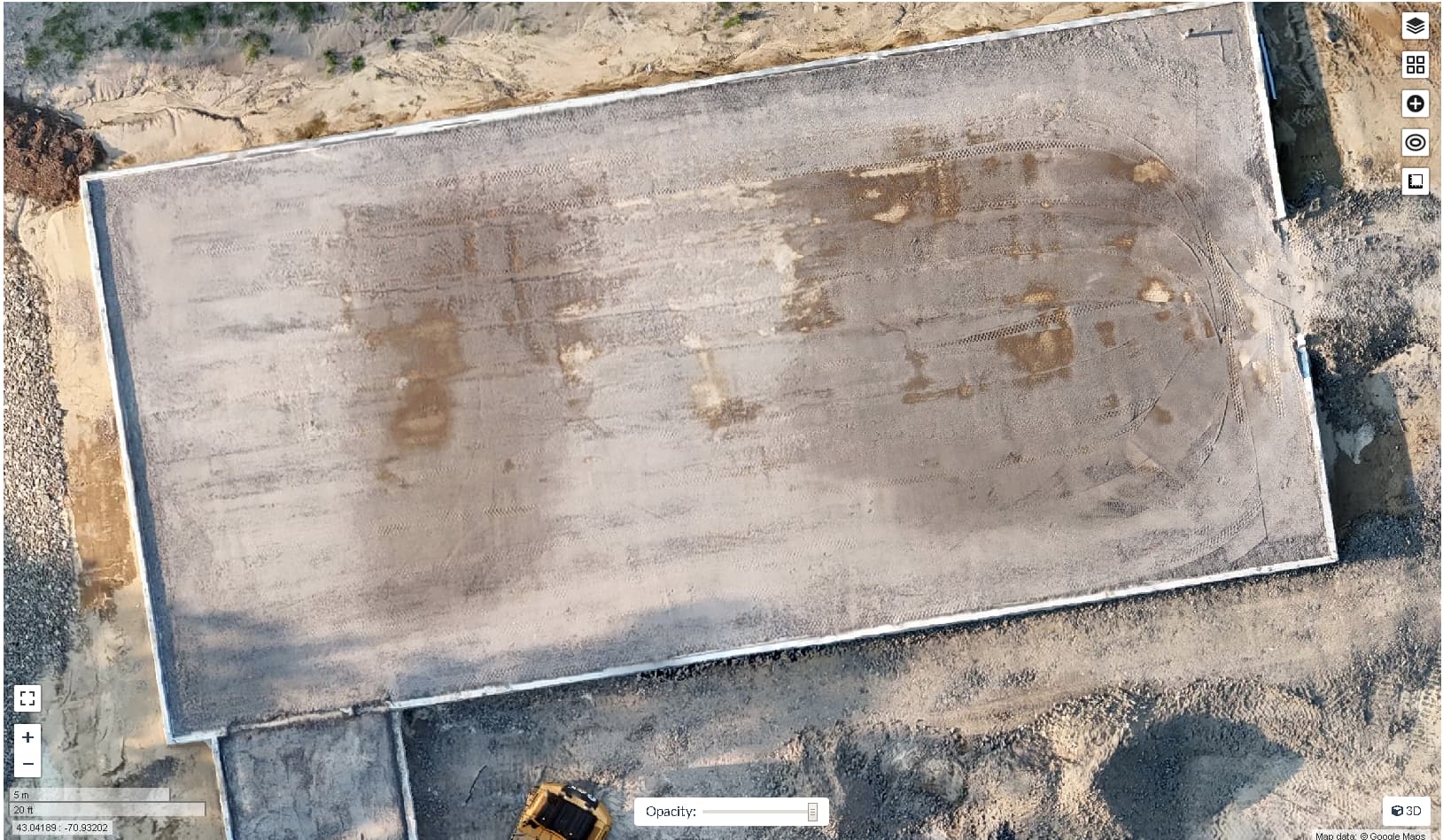
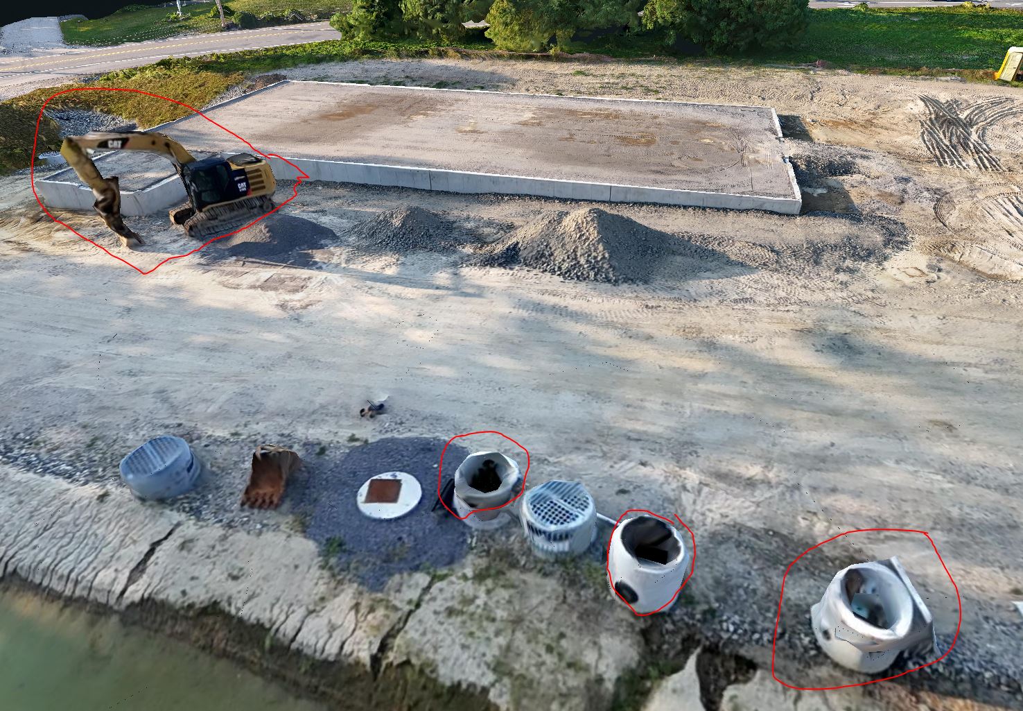
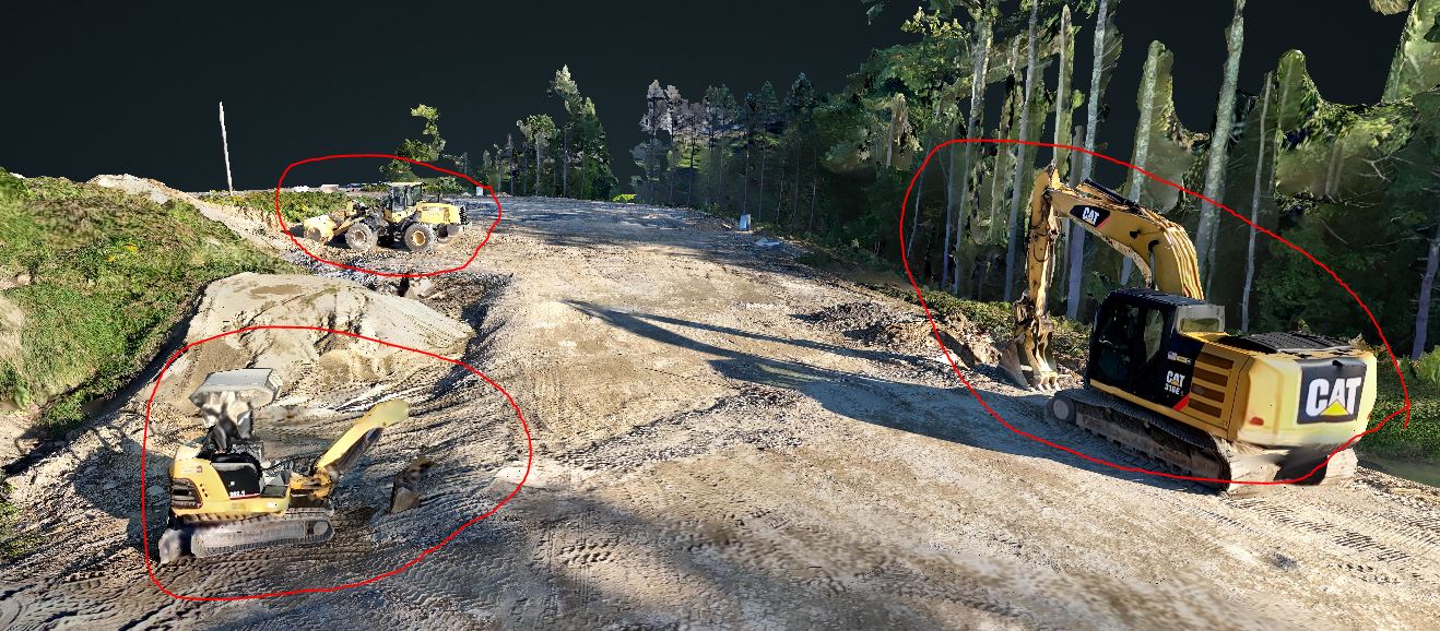
I ran three captures an 80/80 overlap Grid -90 NADIR with the waypoint adjusted to be 200ft AGL, then a circle flight pattern at 200ft AGL -45 NADIR with a radius that covered the majority (~200ft total circumference) of the site looking toward a POI in the center, then another circular at 100ft AGL -20 NADIR with a 100ft circumference looking towards the center of the site. I then took a handful of closer and random camera tilts of the structure starting to be built, trying get good images of the vertical surfaces.

I think I am doing A LOT better than how I started doing this

I can give you more details on the other previous captures if needed, but I am hoping to focus on the last one and how to improve. My next capture I am trying to get it as close to noon to reduce the shadows as possible.

Here are the details asked for, let me know if I can add anything else

  1. Include a link to your images! No images = difficult to help.
    NH108_Source_Pics_20230908.zip - Google Drive

  2. Copy/paste the entire task output (not just parts of it) for everyone to read.
    https://drive.google.com/file/d/1oCbGcRH_dsmnz988BE46uA_KXoUZAoer/view?usp=drive_link

The report is here

  1. Did you fine tune any parameters? Which ones?

Here are the parameters I edited, I am trying to get the highest quality otho and 3D models without capturing 600+ photos.

3d-tiles: true, auto-boundary: true, dem-euclidean-map: true, dem-resolution: 2.0, dsm: true, dtm: true, orthophoto-cutline: true, orthophoto-resolution: 2.0, pc-classify: true, pc-quality: ultra, pc-rectify: true, tiles: true, use-3dmesh: true
  1. If applicable, what browser are you using? What operating system? How did you install the software? Be precise.
  • I use FireFox as primary, but use Chrome if there are issues with FF.
  • Windows 10
  • Purchased and using the windows installer version of WebODM

Thank you for reading all of this, and I look forward to any advice you might be able to provide.

4 Likes

You need to make this accessible for anyone with the link so that it can be accessed by others here.

Even better would be to capture your images in light overcast conditions, which evens out illumination, but midday sun gives very contrasty light with very dark shadows under trees etc.

2 Likes

Would you like to borrow my “No Tinker” setup?

We can arrange mailing it to you.

1 Like

Yes, if that is an option. Let me know what you need

3 Likes

Done

Good idea, now if I could only control the weather!

3 Likes

I ran your dataset with these settings and got quite good results. The shadows aren’t really an issue at the current stage of progress

[Bittersweet Kennel - 07/09/2023] 133 03:58:08

|Options:|auto-boundary: true, dem-resolution: 1, dsm: true, dtm: true, feature-quality: ultra, gps-accuracy: 8, mesh-octree-depth: 13, mesh-size: 500000, min-num-features: 12000, optimize-disk-space: true, orthophoto-resolution: 1, pc-quality: ultra, pc-rectify: true, use-3dmesh: true|
|Average GSD:|1.98 cm|
|Area:|32,389.11 m²|
|Reconstructed Points:|66,746,590|

3D video

2 Likes

So your saying there isn’t anything I can do better? well, other than the previous doing the scan on an overcast day.

So as the building goes up its going to be more important to run the scan closer to noon on an overcast day. Are there other things I should take into consideration as things change?

I have been poking at the manual trying to figure out the differences between our settings, can you tell me why you use these settings? or link me to the documents that you read that helped you determine

It seems like all of the 3D objects that have some sort of tearing from the run with my setting, I am rerunning my capture with your setting now


these settings.

2 Likes

Everything derives from the pointcloud, so focus on getting that right, and inspect that first.

If it looks good, then you can tune the mesh-octree-depth (very very resource intensive, so do this last) and the mesh-size parameters to make the mesh have more vertices.

1 Like

I’d fly lawnmower pattern with the camera at -75 or -80 rather than nadir, and a lower flight at say -45, rather than the circles, making sure you cover the entire area of interest.

In overcast conditions, time of day is not so important.

Once you start to have overhanging areas- under the eaves etc, you may need to take some photos from ground level with a good camera, or the hand-held drone if you want full coverage, otherwise there will be holes in the 3D model. You need to be sure there is plenty of overlap to tie all the photos together- aim for each point to be covered from 5 different viewpoints.
Some from the ground photos would be good for filling in the trees a bit more too.

Mostly just experience with what works for me.
Using ULTRA for feature extraction didn’t make a huge difference with the absolute accuracy, but did improve relative accuracy significantly.

Re Saijin_Naib’s comments above, I would not go to past mesh octree depth 13, as 14 always fails for me, but going higher with the mesh size is OK.

2 Likes

So would this be another Lawnmower pattern below the tops of the trees? Tops of the trees around the site is about 125ft, maybe at 80-100 ft?

1 Like

I notice the circles are a bit offset from the building, particularly the lower one, such that the end of the building, and the excavator, is missed, so you need to make sure all the areas of interest are properly covered.

If you do the top flight at 200’, then the lower one at -45° could be around 130’.

There isn’t really much benefit in having too much height discrepancy between flights, as the GSD is fixed across the final output. Going too low with a smaller subset wont improve the GSD, and at -45 the range to the centre of the image from 130’ will be similar to the centre of the -80°ones from 200’.

Remember that anything standing high above the ground will have less overlap unless you account for it by taking extra photos.

Extra photos from varying angles concentrating on things with complex shapes like the excavator can improve their appearance

2 Likes

I had similar questions when I started and I found this document useful.

I typically fly crosshatch (double lawnmower with 1 set perpendicular to the other) pattern nadir images.

Then I fly the “big box/little box” pattern to capture oblique 30-35 degree images, as noted in the linked document. I aim for 10 percent oblique, 90 percent nadir for the final dataset.

Before I switched to this method I usually used slightly-off nadir images, but the document I linked suggests a combination of nadir and oblique is better.

5 Likes

I can’t thank you enough for this document, I have been reading/highlighting/and re-reading sections of this document every night!

when I read this section:

Some authors have suggested that increasing overlap or including cross-strips in airborne image
blocks can help reduce systematic errors due to higher redundancy. Others have noted that
increased overlap results in shorter baselines (distance between adjacent photos) and subsequently
narrower angles of ray convergence, ultimately subjecting calculated object space locations to errors,
especially in depth/height. Our results suggest that increasing overlap may slightly lower
the standard deviation in nadir-only scenarios, but an increase in the number of
images does not linearly increase accuracy and systematic doming errors remained clearly visible,
regardless of overlap.

I realized I have been doing this ALL wrong! I was up to an 85/85 overlap trying to improve things. That is when I found a post about adding circle captures to slight off set of NADIR, that was great cause it was fairly accurate and very quick to capture. But after reading this paper, I likely introduced a vary large amount of deviation from what should be accurate.

The 10% oblique is is correlation to what? the job site, the object of focus, to the cross-hatch pattern?

for the box patterns, who large do you make them? do you fly these encompass the entire site or do you make multiple boxes that are say 50ftx50ft / 25ftx25ft and cover the site with these boxes?

2 Likes

thank you for taking the time to look at the data and offer this advice, it is very much appreciated.

Right now I am just doing this for fun, but when I showed my brother who works in construction, “the funky looking excavator” was the fist thing he pointed out. /roll_eyes, Then I showed him some measurement, area calculation, and volumetric sizing tools…then he was interested :smiley:

Thank you.

2 Likes

The 10% refers to amount of oblique images in the dataset. So first I plan my cross hatch flights for nadir images and note how many images. If it is 1000, then I aim for 100 oblique images.

The “big box” follows the outer perimeter of the cross hatch flights, with the aircraft flying sideways so that the camera is perpendicular to the flight path and pointing inward for each segment. The little box is an inner offset of the big box, flying somewhat half way toward the center. Inner box also flying sideways, pointing inward. There is a sketch of this arrangement in that paper.

One thing I should have mentioned is this that a flight plan like this may be better suited for orthophotos and dem’s, but may not be nearly as good for full 3d modelling as there probably aren’t enough obliques to texture all objects.

1 Like

oooohhh, ok /slap_forehead that makes more sense!

Got it, if my NADIR flight plan estimates 200 photos of a site, I plan to take ~20 Oblique photos. Have you found that there is a limit to the effectiveness or if they start causing problems if you add more than the 10% obliques say 15, 20 or even 30% oblique shots?

Yes, but what if your site isn’t exactly square. Would the process benefit from having multiple squares back to back across a site? or am I just thinking about this wrong?

yeah, when I saw those patterns on page 6, I wish they had tested an A+E patterns (BoxO + Double Arcs). I think this data may have been interesting.

Its hard to argue with the data showing such a significant increase in the accuracy and decrease in the deviation of the 90/70 overlap with NADIR + 35deg BoxIO.

Thank you so much for taking the time to answer my questions.

1 Like

Yes, but what if your site isn’t exactly square. Would the process benefit from having multiple squares back to back across a site? or am I just thinking about this wrong?

I find that square or rectangular flight paths are more efficient. Polygons with 5, 6,. 7+ are fine and I do those often, but the more segments the polygon has, the less efficient the flight paths become. So I usually chop sites up into rectangular flight boundaries where possible. Regardless, I always fly the perimeter for obliques, even if it isn’t rectangular. It’s more the perimeter and then a smaller inner offset of the perimeter. Its just for square sites that it is a “box”.

1 Like

Thank you so much, this makes SOO much more sense to me now. I am hoping to run a new capture in the next few days using all of this knowledge.

2 Likes

Gordon and luc23 I can’t thank you enough for your time, advice, and links to reading materials! (I hope a side effect is my ability to properly use the NADIR term in a conversation…please correct me if I am wrong)

I have ran a crosshatch pattern (I’ve dubbed the “baseball field lawnmower” :wink: ) at NADIR (camera tilt @-90deg), I then ran a BoxOI pattern with the camera tilt at NADIR+35deg (which if my math was right was -55deg).

Because you both said,

I don’t need it to be good for 3D modeling, I just want it to not make construction worker cringe when the see the equipment they are working with daily. :smiley: To help get more texture, I ran a few circular patterns around all of the equipment and tried to manually get 50% overlapping images of the current “sides” of the building to help get these textures.

But I can see from how the little excavator looks vs the other equipment came out, I need some more practice at doing this manually! But the bigger ones came out OK.

Here is the data from my last run:
Source Images
ODM Quality Report
Console Output
Orthophoto

I think I know what happened to the little excavator, when I looked back at the source images, in many of the photos anything that is missing from the 3D model when it was photoed, there were a large amount of dark shadows mostly covering the missing/warped spots. (If I could only control the clouds or run the capture before 4pm!)

My next things to figure out is with almost 300 more photo’s with my 2nd capture, why is there almost 350 thousand less Sparse Reconstructed Points than the 1st run? And then there is 138Million Dense Reconstructed Points in the 2nd run, I expected to find more points in both sets due to the increased amount of data.

And then why is the Detected and Reconstructed features of the 2nd run SOO much less than the 1st run? With so much extra data I would assume that there would be more in the 2nd run.

and then the GPS errors increased! ???why?? did my random photos for excavator texture add to this?

1 Like

What am I looking for when I inspect the pointcloud? right now when I look at it, I just see what looks like a dot painting of the ortho. How would I go about changing it to get that right first?

Do you have a recommendation in the step changes I should make tuning the mesh-octree-depth and mesh-size parameters?

1 Like